Cold weather is not the best weather for working with epoxy, and rain weather makes it all but impossible. The PT Boat project is now beginning the ninth year and has recently drawn friendly, neighborly comments like, “Why has the project stopped?” But the project has not stopped. On the contrary, there is much work to do, even on an inclement day. Under the boat for example, six stations need to be built to support docking cleats. The best time to do this is while the boat is upside down — it is easier; other things are too. Certain areas need sanding and bulkhead stringers need filling. And on a rainy day, there is always time to think about the engine installation.
Each diesel engine will rest on two stringers; stringers to be eight by eight inches by 34 feet long of treated yellow pine. One end of each stringer will butt into the transom and the other end into the beam frame. The stringers will rest on floors –across nine frames that are spaced one meter apart. But what about athwart ship spacing between stringers and the distance each pair of stringers makes between the keel and outer bulkhead? Where these stringers are placed is very important. This positioning will determine propeller spacing. The distance forward and aft that the engines are installed determines the drive shaft angle. (And even though the entire stringer length will support the engine weight, it is desirable that the engines rest equally over the three reinforced supporting frames.) Once propeller positioning is approximated, the keel and skeg can be accurately tapered, to prevent air from entering under the boat and into the props, which when turning the craft could cause serious cavitation problems.
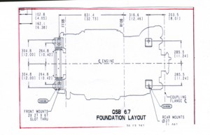
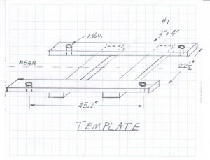
Spacing between stringers is determined by the actual spacing between (engine) mounting holes. Cummins, Inc., in the Foundation Layout, provides these distances regarding the QSB series 6.7-liter diesel engine. According to the Foundation Layout, the distance between the front and rear mounting holes is 45.2 inches and between athwart ship mounting holes 22.5 inches. All holes are in the same plane and parallel to the crankshaft. Hole diameters are 1.06 inches. The weight of each engine with gearbox and oil is 2,000 lbs and will need to be set into the boat with a crane. When the time comes to actually drill the holes in the engine stringers, it seems wise and preferable to first build a template.
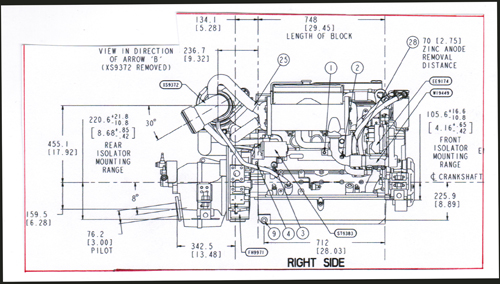
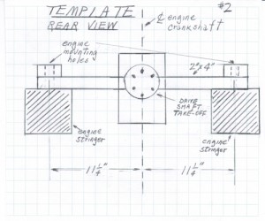
Consider an engine-template and the place where the gearbox “take-off” to the propeller shaft falls, relative to the mounting holes. The Right Side view shows the shaft at an angle of 8 degrees to the engine crankshaft. It may be necessary to increase this angle to within the recommended range of 12-16 degrees. From high school trigonometry, the calculation results in a front engine-mount rise of 3 inches to provide an extra 6 degrees of lift, for a total drive shaft angle of 14 degrees. Cummins provides hard rubber mounts, a capability to raise the front of the engine, and extension ears that allow irregular engine components to fit between stringers. Oil drain plugs (located on the port and starboard lower-ends of the crankcase cover) need to remain unobstructed, as well as the oil heater connection plug. The Rear View sketch now provides enough data to actually make a template. The template will allow the easy positioning of stringers and an awareness of anything the engine might hit, all without actually having an engine, and in plenty of time to make any necessary adjustments.
And so ends another rainy, boat-building day.


